Industrial Fans and the Atex Directive

Concerning Industrial Fans, you cannot help dealing with ATEX, sooner or later.

This acronym (made up by the first letters of the words ATmosphéres and EXplosibles) identifies two different directives of the European Community:

  • No. 2014/34/UE, that became law on the 30th March 2014, which regulates the devices and machinery working in potentially explosive atmospheres, and is directed to manufactures of devices destined to be used around potentially explosive atmospheres; the manufactures must certify these products: the directive before, Directive No. 94/9/CE, has been canceled by this new one, starting from the 20th April 2016;
  • la 99/92/CE, which is directed to the users of certified devices and concerns safety and health of the workers in potentially explosive atmospheres: it is implemented in backgrounds where explosions can actually occur.

The ATEX Regulations indicate the essential requirements that the devices must have concerning safety and health: you can easily realize that respecting these requirements is essential for industrial fans that are installed in backgrounds where explosions can potentially occur.

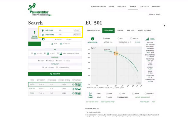
The main suppliers of industrial ventilation systems, including Euroventilatori International, supply certified ATEX fans equipped with all necessary technical documentation.

Before installing an industrial fan you must evaluate the risks concerning the background where the fan is going to work. However, the choice of installing an industrial fan that meets the requirements of the ATEX directive is completely up to the Customer.

In this case, a supplier like Euroventilatori International can best assist and advise the Customer, thanks to its staff of highly qualified technical experts.

Atex zone table

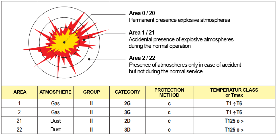
The ATEX zones chart

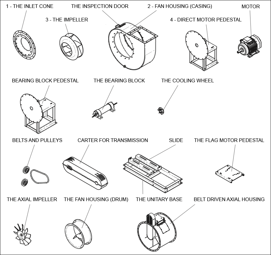
The fans that meet the requirements of the ATEX directive are built following some particular expedients in order to avoid sparks caused by the friction between the spinning part and the fix one; there are different parts and characteristics that are accurately examined before assembling the fan.

Dust zone table

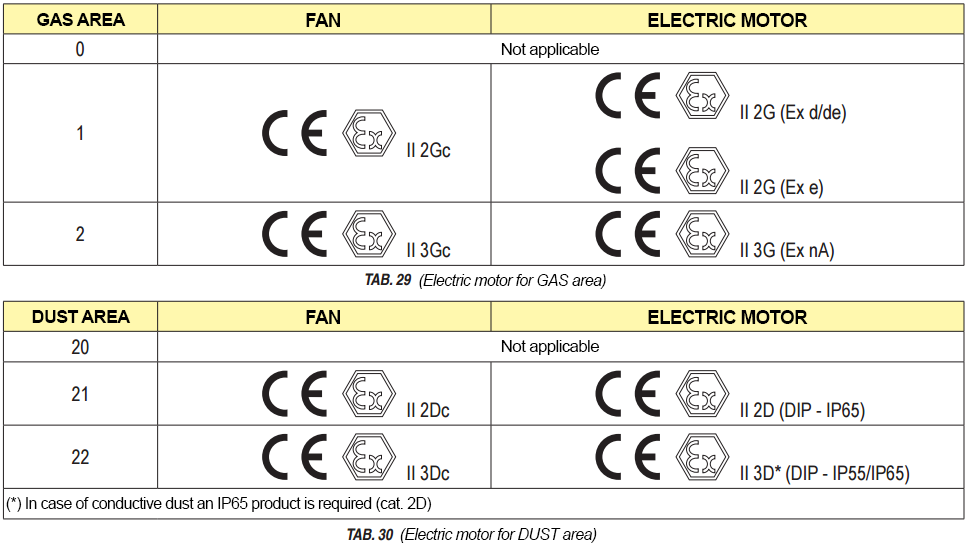
Depending on the background , the ATEX directive indicates the Fan and Motor Type

Furthermore, once the devices are working, accurately planning the maintenance and the cleaning is of fundamental importance, depending on the type of background where the fan works and depending on the materials that are eventually driven in it: dusts are potentially dangerous, because they set down even where mobile and fixed parts are closer and can therefore cause sparks.

Euroventilatori International provides, together with its own certified ATEX fans, all certifications and technical manuals which are necessary in order to best use the device; it can also assist its Customers in extremely short times, through the intervention of its highly qualified staff.

The discharge position of industrial fans

When you talk about the discharge position of an industrial fan you actually refer to the position of the discharge, or rather the output air flow.

An industrial fan is just one of the various elements that make up the ventilation system where it is integrated: in order to convey the air flow, the fan will obviously have to provide a ductwork, and especially both income and output pipes.
The incoming air flow (suction) is almost always clearly defined, while the output air flow (discharge) can be oriented in many different directions, up or down, right or left or even in intermediate directions.

Keeping the other elements unchanged, the shorter the ductwork is, the more effective it is: as a consequence, the choice of the discharge position is generally up to the plant engineer, which can accurately evaluate all the involved features and properly take into consideration the interactions between the various elements of the ventilation system.discharge position of industrial fans

The possible discharge positions are determined, according to international regulation, with an alphanumeric code where the literal part (RD or LG) indicates the direction of rotation of the impeller and the number indicates the angle of the output air flow.
The typical discharge positions are 16, where 8 of them are clockwise rotation (RD) and the other 8 ones counterclockwise rotation (LG): keep in mind that in a centrifugal fan the discharge position must be determined by looking at the fan from the motor side.

Euroventilatori International produces industrial fans in 16 different positions of the delivery mouth: some discharge positions, and precisely RD – LG 180 and 225 are constructed implementing special building adaptations.

Discharge position of industrial fans in indirect Transmission

Discharge position of industrial fans in indirect transmission

Concerning not direct driven fans (all fans with constructive executions where a belt or some other components for transmission are involved to bond the impeller and the motor), the related discharge positions can be chosen according to the standard angles that you can see on the picture.

Discharge position of axial industrial fans

Discharge position of axial industrial fans

In axial fans the angular position of the motor is indicated by the angle (in degrees) between the reference axis orthogonal to the supporting base and the accessory element axis, rotating on the axis of the fan from the point of view of the control side.

The choice of the right discharge position is essential in order to get the best performance from the ventilation system: the right directioning of the discharge will effect the output pipes, which can therefore be as short as possible. That’s why choosing experienced and capable builders of industrial fans, like Euroventilatori International, is fundamental: we can actually provide assistance to our customer since the very first selection phase of the fan which better suits his needs, and assist him all the process of planning and accomplishing of the ventilation system long thanks to our own technical department, our plant engineers and technical experts.

Choosing an industrial fan producer that can assist the customer step by step during the accomplishment of the ventilation system means implementing a really custom-made ventilation system, which has actually been designed on the customer’s needs, that will therefore guarantee the best return of investment and achieved results.

LiveCurve: advanced features to choose an industrial fan

The LiveCurve software performed by Euroventilatori International allows the user to simulate the aeraulic curves for the range of fans that our company produces, in order to be able to make an initial selection of the fan types which are most suitable for his own needs.

livecurve interface and work area

LiveCurve Interface: you can see the working point indicated on the graph and the position of the panel for the selection of air flow and pressure values.

But what makes Livecurve the most advanced software for the simulation of air flow/pressure curves on the market?

As well as the basic features, which have been described in the last post, Livecurve allows the user to simulate and instantly make comparisons among many curves that represent the relation between the two parameters, speeding up the selection process of the most suitable industrial fan.
Let’s get into the possibilities offered by this appliance and let’s take a closer look at some advanced features of this interface: the most captivating element is obviously the Livecurve graphic on the right.
It provides the immediate representation of the air flow/pressure graph, which is developed according to the working point that was selected earlier choosing the required values.
A little orange rectangle on the graph indicates the working point, the point on the graph located by the values you have selected. This point is part of the curve which refers to the chosen fan type, as indicated in the list on the left below on the display.
If we choose a different Fan Type, we will see how the curve changes, since every fan has its own specific curve. Otherwise, the working point will always be the same we have chosen, even if it will be placed differently on the curve we see.

On the Data Panel, on the right, you can find the explanation and summary of the values of air flow, pressure (total, static and dynamic), rotation speed, power (kW), efficiency, noise level and load (static and dynamic) that refer to the working point you have selected.
That is a very important and extremely useful feature: if you move the mouse over the curve and you scroll it, you will see that the information reported on the Data chart, which summarizes all data on the right, will consequently change. This way you can see all the values concerning the relation/ratio of air flow/pressure which refer to the fan type you are currently analyzing.
If you click on a point of the curve, a temporary working point will be set: changing the fan type, it will be maintained for the air flow value and we will immediately obtain the corresponding pressure value.
To identify the conditions where the chosen fan type will work, LiveCurve provides the Utilization Area right above the graph: here you can select the modality (inlet or outlet), change the altitude and the temperature where the fan will work or switch to the inverter mode, where you can explore the graph to find the working point that better fits your needs.
If you want to see also the curves that represent the power and the performance, you only need to choose the related options on the graph panel, where you can even change the units of measurement and the type of visualization, choosing between static curve or dynamic pressure curve, and between logarithmic and linear scale.
Livecurve is an original simulator which allows the user to choose the industrial fan which better fits his needs and to make an initial selection among the items: however it is very important that plant engineers and technical experts analyze each specific case, in order to adapt the features, if necessary, to the customer’s needs and to create this way a real custom-made machinery.

Here is the Video Tutorial on the Euroventilatori International Youtube channel:

Components of Industrial Fans

Components of Industrial Fans
What are the several components of industrial fans and what is their function? In this post we will try to answer this question, analyzing in details the several components of an industrial fan.

The Inlet cone: is a component for directing air into the fan housing. It has usually another function, that i sto link the fan to pipes. Inlet cone dimensions and shapes depend on the type and function of the industrial fan.

The impeller: is the real heart of the industrial fan. It’s a rotating component on which are placed the blades (that can be backward, forward or straight blades, depending on their use).

Fan Housing (or Casing ): the housing is the structure that contains the impeller; the air (or the fluid) to be handled passes through the housing and it moves toward the ventilation system. In particular, the air in the housing is compressed and, consequently, its speed increases. The performance of the fan depends on the physiognomy of the impeller and on the shape of the housing too.

The inspection door: is a small door placed on the case, very useful for inspections or to perform ordinary or extraordinary maintenance.

The motor pedestal: is the support where the fan is installed onto, distinguished between direct motor pedestal (used in direct driven fans) or bearing block pedestal(used in belt driven fans). In fans of big size the pedestal is directly welded on the case.

Consisting of shaft and bearings, the bearing block (support) is the component in charge for the transmission of the industrial fan. The bearing block is stressed by the mechanical forces such as velocity and couple, which are related to the belt drive

The cooling wheel: is a small impeller slipped on the impeller hub for direct driven fans, or on the support shaft for belt driven fans. It is used to dispose of/dissipate the heat of the air flow, which blows through the case, to prevent damages for the most delicate parts, like the engine (bearings and electrical parts) or the support (bearings and mechanical parts).

Belts and Pulleys: they are provided within the “transmission” of the indirect driven fans. They must be chosen by qualified technicians: both the desired performance of the fan and the nominal number of engine revolutions(rpm) affect their choice.

Carter for transmission: its aim is to protect the drive belt by external agents, and simultaneously, to increase the security of the belt arrangement, in this way operators avoid accidental contacts with the moving belt, especially if the belt breaks.

The Unitary base: is the support of the belt driven industrial fan, which acts as a support base for the installation of the industrial fan. The bedplate connects the motor and the belt driven fan in a single base (or foundation).

The Flag motor pedestal: is a base of the motor on the side of the chair. The motor is fixed on it.

The axial Impeller: is the rotating component of axial fans (which are provided with airfoil blades in aluminum die castings). The air flow meets and leaves the impeller along surfaces which are coaxial to the air flow itself.

The Fan Housing (or drum): is the housing of the axial flow fan, which includes a welded base for the engine, to create the axial air flow.

Belt driven axial housing: is the belt driven version of the drum. The support is fixed on the base, and through the transmission it is connected to the external engine.

Centrifugal, axial and double stage fans: a tecnical classification

High-pressure double stageIn post “Industrial Fans explained to the laymen/ non insiders”, we have provided a very simplified description of the industrial fans, and we have added an essential classification too. In this post we want to provide a more technical explanation, defining the industrial fans with more specialized terms and classifying them accordingly.

In this situation, we can define the industrial fan (hereinafter: fan) as a turbomachine that receives mechanical energy and then uses it, thanks to a bladed impeller, in order to maintain a continuous flow of air or other gas passing through it, providing a work per unit mass that is not greater than 25 kJ / kg (UNI EN ISO 13349).

There are several ways of classifying industrial fans:

Classification based on the performance of the flow in the impeller:

  • Centrifugal fans: in these fans the fluid enters the impeller with axial direction and leaves it in a direction perpendicular to the axis. The double stage is a particular configuration of the centrifugal fans (see the image in evidence) in which two impellers and therefore two different stages of compression are used;
  • Axial fans: in these fans the air enters and exits the impeller along surfaces that are cylindrical and coaxial with the same fan.

Classification based on the drive system:

  • Belt driven Fan
  • Direct driven Fan (directly coupled with the electric motor)
  • A particular system is the system with the coupling joint; it typically consists of a female plus a male part. The female part is installed with a plug to the bearing block, differently the male one is installed to the shaft of the electric motor.

Classification based on the maximum pressure delivered:

  • Fans with low pressure (maximum pressure delivered: about 300 mmCA)
  • Fans with medium pressure (maximum pressure delivered: about 600/700 mmCA)
  • Fans with high pressure (maximum pressure delivered: about 2500 mmCA)

Backward blades, forward blades, straight blades to industrial fans

industrial fans bladesIn the post “Industrial fans explained to non insiders / laymen” we introduced the distinction between axial and radial or centrifugal fans.  In this post we will exclusively deal with radial fans, and in particular, with the blades included in the impeller.
You should keep in mind that in radial fans, the air (or the fluid) meets the impeller in axial direction and leaves it perpendicularly  to the axis of the fan.
In this context, blades are fundamental. They are divided into three categories:

  • Backward blades: in this type of impeller, the fluid is driven by the convex part of the blades (the back).
  • Forward blades: in this type of impeller, the fluid is driven by the concave part of the blades (the front).
  • Straight blades: impeller where the fluid is processed  indistinctly with the back or front side

Concerning the performance, using negative blades involves a lower absorbed power and therefore a lower energy consumption: they typically offer an higher performance.  In the same way, at equal range and size, the forward curved fan offers an higher performance concerning pressure, but also an higher absorbed power, and therefore an higher energy consumption.

How to choose an industrial fan (part one)

how_to_choose_an_industrial_ fan_part_one

Can’t you figure out how to choose an industrial fan? Here you are some tips.


Check out the four main parameters determining the features of an industrial fan to choose the industrial fan suitable for a specific application.

These four parameters are:

  • Flow rate
  • Pressure
  • Power
  • Performance

Let’s see these four parameters in detail, as clearly as possible, using common language.

    • Flow rate

The flow rate is the quantity of air passing through an industrial fan over time: in the metric system, it is expressed in cubic meters processed in a second, a minute or an hour. It is the main parameter, as it defines for the field operators “the purpose” for which the industrial fan has been created.

    • Pressure

The pressure is the form of energy enabling the fan flow rate to flow into the circuit where the fan is applied. In other terms, think of the pressure of a fan as of the blood pressure, made by the pulse of the heart, to enable the blood flow (the flow rate) to reach all parts of the body.

    • Power

After setting the required combination between flow rate (which performs the work) and pressure (which allows the flow rate to do the work), it’s time for the power to apply to the fan. The power is the energy used to drive the impeller, in order to achieve the required combination between flow rate and pressure.

    • Performance

As you know, in nature energy can neither be created nor be destroyed but rather transformed. Particularly, not all of the energy delivered to run an industrial fan is transferred to the fan itself:
a part of it is converted into heat due to the friction of the engineering parts (and to other factors) and then dispersed. Thus, the performance is the ratio of the energy that the industrial fan actually transfers to the air mass and the energy dispersed by the energy resource (in our case nearly always an electrical motor).

Interesting, isn’t it? For more details on the parameters defining the industrial fans and their choice, see the part two of this post and the Glossary, both forthcoming.

The industrial fans explained to non-experts

the industrial fans explained to non experts
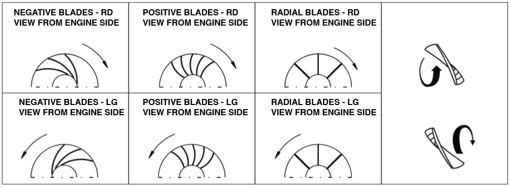
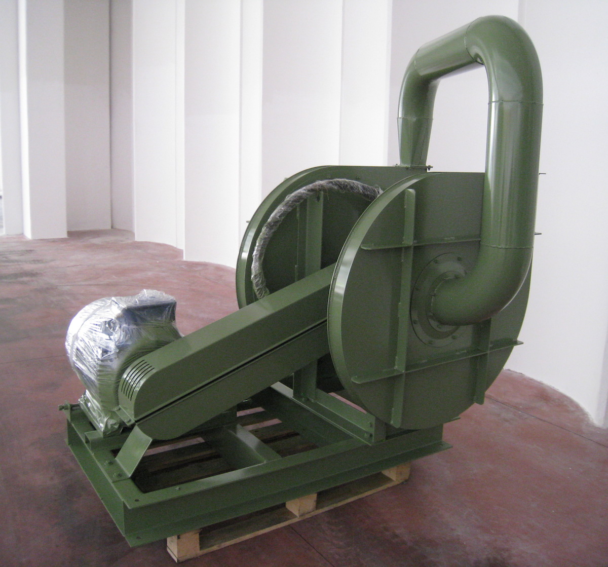
Industrial fans are machines whose rotating blades are driven by an electrical motor (hence the name “electric fan”). The primary functions of these fans are to provide a continuous large flow of gas, such as clean air or dusty air, and to transport particulate floating in a gas flow, such as wood chips.

These fans may have fan wheels/impellers that range from a few tens of centimeters to several meters, and are typically used both inside of machines, industrial equipment and inside of plants for the industrial fans, for which they are essential parts of.

In terms of construction, most industrial fans can be categorized into one of two general types:

  • axial industrial fans: the gas fluid is sucked and moved parallel to the fan wheel’s shaft;
  • centrifugal or radial industrial fans: the gas fluid is sucked in the direction of the impeller’s axis and then moved perpendicular to the fan wheel’s shaft

The installers of industrial fan plants are used to categorizing the industrial fans according to their pressure range

In detail, industrial fans can be:

  • low-pressure industrial fans (up to about 300 mmWC)
  • medium-pressure industrial fans (up to about 600/700 mmWC)
  • high-pressure industrial fans (up to about 2500 mmWC)

Finally, just note that there are 4 basic values defining an industrial fan: flow rate, pressure, performance and rotation speed. These four features are critical in selecting an industrial fan; for more details on this topic, see this article from industrial-fans-blowers.com.

Industrial-fans-blowers.com is born, the first blog dedicated to industrial fans blowers

industrial-fans-blowers.com is bornIndustrial-fans-blowers.com is the first blog wholly dedicated to the industrial, commercial and technical aspects of the industrial fans blowers and, more generally, of the world of industrial fans applied to machinery, plants and environments.

Designed by Euroventilatori International Spa, international leading company in the world of industrial fans, Industrial-fans-blowers.com wants to be a valuable resource for students, fitters, designers, engineers, installers and in general, for the entire community of people who perform professional or training activities relating to the world of industrial fans.

Industrial-fans-blowers.com will include informative articles, technical insights, product and field news. Our goal is to share leading and accessible viewpoints on the world of the industrial fans with the community of field experts, as well as to map out considerations, promote the sharing and the spreading of technical information and above all, get the field operators communicate to ease the circulation of ideas … as well as of air flows.