The discharge position of industrial fans

When you talk about the discharge position of an industrial fan you actually refer to the position of the discharge, or rather the output air flow.

An industrial fan is just one of the various elements that make up the ventilation system where it is integrated: in order to convey the air flow, the fan will obviously have to provide a ductwork, and especially both income and output pipes.
The incoming air flow (suction) is almost always clearly defined, while the output air flow (discharge) can be oriented in many different directions, up or down, right or left or even in intermediate directions.

Keeping the other elements unchanged, the shorter the ductwork is, the more effective it is: as a consequence, the choice of the discharge position is generally up to the plant engineer, which can accurately evaluate all the involved features and properly take into consideration the interactions between the various elements of the ventilation system.discharge position of industrial fans

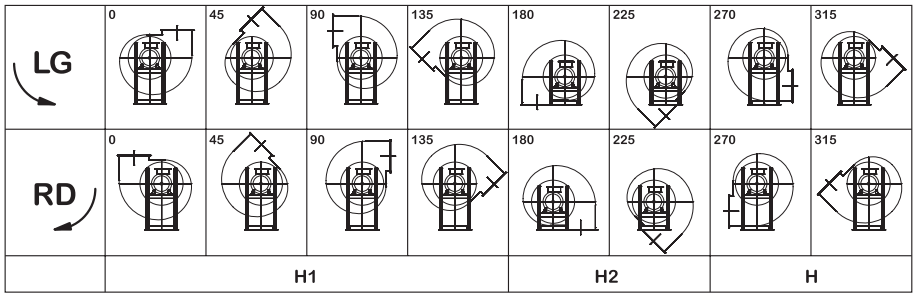
The possible discharge positions are determined, according to international regulation, with an alphanumeric code where the literal part (RD or LG) indicates the direction of rotation of the impeller and the number indicates the angle of the output air flow.
The typical discharge positions are 16, where 8 of them are clockwise rotation (RD) and the other 8 ones counterclockwise rotation (LG): keep in mind that in a centrifugal fan the discharge position must be determined by looking at the fan from the motor side.

Euroventilatori International produces industrial fans in 16 different positions of the delivery mouth: some discharge positions, and precisely RD – LG 180 and 225 are constructed implementing special building adaptations.

Discharge position of industrial fans in indirect Transmission

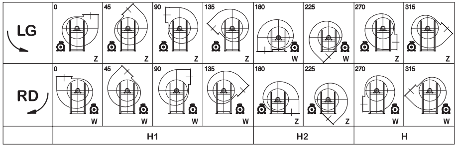
Discharge position of industrial fans in indirect transmission

Concerning not direct driven fans (all fans with constructive executions where a belt or some other components for transmission are involved to bond the impeller and the motor), the related discharge positions can be chosen according to the standard angles that you can see on the picture.

Discharge position of axial industrial fans

Discharge position of axial industrial fans

In axial fans the angular position of the motor is indicated by the angle (in degrees) between the reference axis orthogonal to the supporting base and the accessory element axis, rotating on the axis of the fan from the point of view of the control side.

The choice of the right discharge position is essential in order to get the best performance from the ventilation system: the right directioning of the discharge will effect the output pipes, which can therefore be as short as possible. That’s why choosing experienced and capable builders of industrial fans, like Euroventilatori International, is fundamental: we can actually provide assistance to our customer since the very first selection phase of the fan which better suits his needs, and assist him all the process of planning and accomplishing of the ventilation system long thanks to our own technical department, our plant engineers and technical experts.

Choosing an industrial fan producer that can assist the customer step by step during the accomplishment of the ventilation system means implementing a really custom-made ventilation system, which has actually been designed on the customer’s needs, that will therefore guarantee the best return of investment and achieved results.

Components of Industrial Fans

Components of Industrial Fans
What are the several components of industrial fans and what is their function? In this post we will try to answer this question, analyzing in details the several components of an industrial fan.

The Inlet cone: is a component for directing air into the fan housing. It has usually another function, that i sto link the fan to pipes. Inlet cone dimensions and shapes depend on the type and function of the industrial fan.

The impeller: is the real heart of the industrial fan. It’s a rotating component on which are placed the blades (that can be backward, forward or straight blades, depending on their use).

Fan Housing (or Casing ): the housing is the structure that contains the impeller; the air (or the fluid) to be handled passes through the housing and it moves toward the ventilation system. In particular, the air in the housing is compressed and, consequently, its speed increases. The performance of the fan depends on the physiognomy of the impeller and on the shape of the housing too.

The inspection door: is a small door placed on the case, very useful for inspections or to perform ordinary or extraordinary maintenance.

The motor pedestal: is the support where the fan is installed onto, distinguished between direct motor pedestal (used in direct driven fans) or bearing block pedestal(used in belt driven fans). In fans of big size the pedestal is directly welded on the case.

Consisting of shaft and bearings, the bearing block (support) is the component in charge for the transmission of the industrial fan. The bearing block is stressed by the mechanical forces such as velocity and couple, which are related to the belt drive

The cooling wheel: is a small impeller slipped on the impeller hub for direct driven fans, or on the support shaft for belt driven fans. It is used to dispose of/dissipate the heat of the air flow, which blows through the case, to prevent damages for the most delicate parts, like the engine (bearings and electrical parts) or the support (bearings and mechanical parts).

Belts and Pulleys: they are provided within the “transmission” of the indirect driven fans. They must be chosen by qualified technicians: both the desired performance of the fan and the nominal number of engine revolutions(rpm) affect their choice.

Carter for transmission: its aim is to protect the drive belt by external agents, and simultaneously, to increase the security of the belt arrangement, in this way operators avoid accidental contacts with the moving belt, especially if the belt breaks.

The Unitary base: is the support of the belt driven industrial fan, which acts as a support base for the installation of the industrial fan. The bedplate connects the motor and the belt driven fan in a single base (or foundation).

The Flag motor pedestal: is a base of the motor on the side of the chair. The motor is fixed on it.

The axial Impeller: is the rotating component of axial fans (which are provided with airfoil blades in aluminum die castings). The air flow meets and leaves the impeller along surfaces which are coaxial to the air flow itself.

The Fan Housing (or drum): is the housing of the axial flow fan, which includes a welded base for the engine, to create the axial air flow.

Belt driven axial housing: is the belt driven version of the drum. The support is fixed on the base, and through the transmission it is connected to the external engine.

How to choose an industrial fan (part one)

how_to_choose_an_industrial_ fan_part_one

Can’t you figure out how to choose an industrial fan? Here you are some tips.


Check out the four main parameters determining the features of an industrial fan to choose the industrial fan suitable for a specific application.

These four parameters are:

  • Flow rate
  • Pressure
  • Power
  • Performance

Let’s see these four parameters in detail, as clearly as possible, using common language.

    • Flow rate

The flow rate is the quantity of air passing through an industrial fan over time: in the metric system, it is expressed in cubic meters processed in a second, a minute or an hour. It is the main parameter, as it defines for the field operators “the purpose” for which the industrial fan has been created.

    • Pressure

The pressure is the form of energy enabling the fan flow rate to flow into the circuit where the fan is applied. In other terms, think of the pressure of a fan as of the blood pressure, made by the pulse of the heart, to enable the blood flow (the flow rate) to reach all parts of the body.

    • Power

After setting the required combination between flow rate (which performs the work) and pressure (which allows the flow rate to do the work), it’s time for the power to apply to the fan. The power is the energy used to drive the impeller, in order to achieve the required combination between flow rate and pressure.

    • Performance

As you know, in nature energy can neither be created nor be destroyed but rather transformed. Particularly, not all of the energy delivered to run an industrial fan is transferred to the fan itself:
a part of it is converted into heat due to the friction of the engineering parts (and to other factors) and then dispersed. Thus, the performance is the ratio of the energy that the industrial fan actually transfers to the air mass and the energy dispersed by the energy resource (in our case nearly always an electrical motor).

Interesting, isn’t it? For more details on the parameters defining the industrial fans and their choice, see the part two of this post and the Glossary, both forthcoming.

The industrial fans explained to non-experts

the industrial fans explained to non expertsIndustrial fans are machines whose rotating blades are driven by an electrical motor (hence the name “electric fan”). The primary functions of these fans are to provide a continuous large flow of gas, such as clean air or dusty air, and to transport particulate floating in a gas flow, such as wood chips.

These fans may have fan wheels/impellers that range from a few tens of centimeters to several meters, and are typically used both inside of machines, industrial equipment and inside of plants for the industrial fans, for which they are essential parts of.

In terms of construction, most industrial fans can be categorized into one of two general types:

  • axial industrial fans: the gas fluid is sucked and moved parallel to the fan wheel’s shaft;
  • centrifugal or radial industrial fans: the gas fluid is sucked in the direction of the impeller’s axis and then moved perpendicular to the fan wheel’s shaft

The installers of industrial fan plants are used to categorizing the industrial fans according to their pressure range

In detail, industrial fans can be:

  • low-pressure industrial fans (up to about 300 mmWC)
  • medium-pressure industrial fans (up to about 600/700 mmWC)
  • high-pressure industrial fans (up to about 2500 mmWC)

Finally, just note that there are 4 basic values defining an industrial fan: flow rate, pressure, performance and rotation speed. These four features are critical in selecting an industrial fan; for more details on this topic, see this article from industrial-fans-blowers.com.